Fritzing


 (348 votes, average: 3.65 out of 5)
About Fritzing
Most electronics design tools assume you already know how to read a schematic. They open to a blank canvas, hand you a symbol library, and expect you to draw a circuit using the standard notation that engineers have used for decades. That works fine if you have an engineering background. It works badly if you are a maker, a student, a teacher, or anyone who learned electronics by physically wiring components on a breadboard and now wants to document what they built.
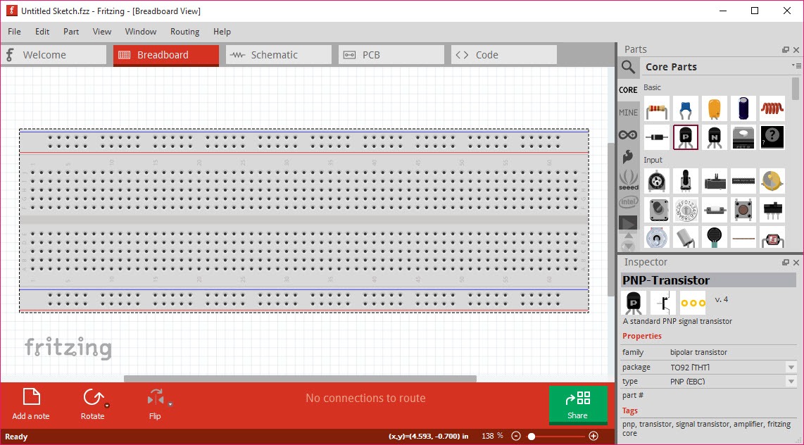
Fritzing is built around the second group. The application opens to a virtual breadboard, a photo-realistic green plastic strip with rows of holes, and the parts library shows components drawn the way they look in real life. A red LED looks like a red LED. An Arduino Uno looks like the actual blue board with the USB and barrel jack drawn on it.
You drag parts onto the breadboard, you draw colored wires between holes the same way you would push jumper wires on a real one, and the document you create looks like a clear photograph of a working prototype rather than an abstract diagram.
That is the central design decision and almost everything useful about the application follows from it.
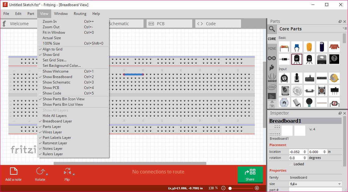
Three views of the same circuit
The breadboard view is the front door, but the application keeps three synchronized views of every project. The schematic view shows the same circuit using standard electronics symbols, the formal notation an engineer would use to publish or read it. The PCB view shows the same circuit as a printed circuit board layout, with copper traces, pads, and a board outline you can size and shape.
The three views are linked. Place a component in the breadboard view, it appears as a symbol in the schematic and a footprint in the PCB. Move a wire connection in the schematic, the breadboard updates.
This is the actual workflow benefit, you can start a project visually on the breadboard, transition to the formal schematic when you want to clean it up, and finish in the PCB view when you are ready to fabricate. Most users start with the breadboard and never really need to leave it, which is fine for a documentation purpose, but the path to a real board is there if you want it.
The parts library, where the application earns its hobbyist following
The bundled parts library is large and skewed heavily toward maker electronics. Arduino boards in every common variant, Raspberry Pi boards, common sensors (temperature, humidity, ultrasonic, IMU, light), motor drivers, relays, LEDs in every color, resistors, capacitors, ICs by family. Each part comes with a breadboard graphic, a schematic symbol, and a PCB footprint, all three views handled by the same part definition.
For components not in the library, a community-contributed catalog adds thousands more, and a custom parts editor lets you build your own. The parts editor is the trickiest piece of the application to learn, you have to provide an SVG for each of the three views, a connector list, and the metadata that ties them together. Doing this well takes time, and the quality of community-contributed parts varies widely. Some are pixel-perfect, some look like rough sketches with misplaced connectors.
For circuit simulation rather than documentation, LTspice is the tool people graduate to once their analog circuits get serious. The simulation features in Fritzing are limited, basic continuity and simple component models, and the application is honest about not competing on that ground.
PCB layout and the realistic ceiling
The PCB view is where the application transitions from a documentation tool to an actual fabrication path. You define a board outline, route the traces (manually or with the built-in autorouter), add a silkscreen layer, and export Gerber files. The output is real, you can send it to a board fabricator and get back a working PCB.
The catch is that the PCB capabilities have a ceiling, and most serious projects hit it. The autorouter is slow and produces routing that looks amateur next to what KiCad or professional EDA software generate. The DRC (design rule check) catches obvious problems but misses the kind of subtle issues that matter in higher-speed or higher-current designs. Two-layer boards work fine, four or more layers are not supported. There is no 3D PCB view to check component clearance, and the silkscreen editor is functional rather than precise.
For a hobby project with a few dozen components and modest electrical demands, the workflow holds up. For anything dense, high-frequency, or commercially manufactured at scale, the tool runs out of headroom.
Knowing where that line is matters more than learning every PCB feature, because the line determines whether Fritzing is the right place to finish the project or just the right place to start it.
Documentation, which is what the application is really for
The honest take after years of community use is that Fritzing is best understood as a documentation tool that happens to also make PCBs. The breadboard view is the killer feature, and the killer use case is producing the kind of diagram you see in maker tutorials, electronics courses, project write-ups, and Arduino books.
A clear visual showing how to wire a circuit is worth more to a beginner than a formally correct schematic, and this application has become the standard tool for producing those visuals.
Export options support that use, PDF, PNG, SVG, and EPS all work, with transparent background options and adjustable resolution. The SVG export is clean enough that the diagrams can be further edited in Inkscape for inclusion in published materials, books, or course notes. The BOM (bill of materials) export lists every component in the project, useful for kit assembly or part ordering.
For the broader maker workflow, once the circuit works on breadboard and the design is documented, the next steps usually involve building a physical enclosure.
FreeCAD handles the 3D modeling and Cura slices the result for 3D printing. Fritzing does not pretend to cover any of that, it stops at the electronics.
The donation model that changed the conversation
The download distribution model shifted toward a pay-what-you-want with a minimum donation. The application itself stayed open source, anyone could still build it from source for free, but the precompiled binaries moved behind a small required contribution. This was contentious in the community, and the discussion around whether the application is still “free” depends on whether you count “can you compile it yourself” as free access.
The practical answer for most users is that the donation amount is small, the source code remains open under GPL, and the project funds development that would otherwise depend on volunteer time. The change is real, the framing of it as a problem usually says more about the expectations of free software users than about the application itself.
Conclusion
Fritzing found its niche by being the tool that explains an electronics project rather than the tool that engineers one. The breadboard view turned circuit documentation into a visual language a beginner can read on first sight, and the application’s success has come from being treated as the documentation standard for maker tutorials and educational materials rather than as a competitor to professional EDA suites.
For makers, teachers, students, and hobbyists building projects around Arduino, Raspberry Pi, or similar prototyping platforms, the application is the right answer for most documentation needs and for small PCB projects.
For engineering work that pushes beyond two layers, demands serious DRC, or needs reliable autorouting, it is the wrong tool and trying to force it produces frustration. The application is clear about what it is good at, and the community has built around that clarity.
Treating it as the documentation and small-scale PCB tool it actually is makes the limitations easy to accept, treating it as a general-purpose EDA replacement makes them feel like flaws. Same application, different expectations, different verdict.
Pros & Cons
- The breadboard view is genuinely unique, no other electronics tool produces the same kind of visual documentation
- Three synchronized views (breadboard, schematic, PCB) let you work in whichever paradigm makes sense for the moment
- Large built-in parts library skewed toward maker electronics, with community-contributed extensions
- PCB view exports real Gerber files that any fabrication service can manufacture
- SVG, PDF, and PNG exports are clean enough for books, courses, and project documentation
- Custom parts editor exists for components not in the library, even if it has a learning curve
- PCB capabilities top out at two layers and the autorouter produces unimpressive results
- Limited simulation, not a substitute for SPICE-based tools
- DRC catches obvious errors but misses subtle issues that matter in serious designs
- Memory use climbs steeply with large schematics, large projects can become sluggish or crash
- Community-contributed parts vary widely in quality, some need cleanup before they are usable
- The mandatory donation download model has alienated part of the user base, even though the source remains open
Frequently asked questions
The breadboard view. No other widely used electronics tool produces the kind of visual prototype documentation that makes a circuit understandable to someone who has not memorized standard schematic notation. For tutorials, classrooms, hobbyist project write-ups, and Arduino-style maker work, the visual breadboard is the entire reason to use this application.
Yes. The PCB view exports standard Gerber files that any fabrication service accepts. The limitations are on what kinds of boards you can design (two layers maximum, modest trace routing complexity), not on whether the export format works. Simple boards manufacture without issues.
Only at a basic level. The application can check for some electrical errors and run simple simulations on certain component types, but it is not a SPICE-class simulator. Serious analog or mixed-signal simulation needs a dedicated tool, the documentation-and-prototyping workflow is the application's actual strength.
The community-contributed parts catalog extends the bundled library with thousands of additional components. For something truly unusual, the custom parts editor lets you build a new part with all three views (breadboard graphic, schematic symbol, PCB footprint). The custom editor takes time to learn, but the workflow is documented and a working part can be saved and reused.
Performance drops noticeably as projects grow, and very large projects sometimes become unstable. For a few dozen components, performance is fine. For a busy circuit with many ICs and dense wiring, expect slower response and occasional issues. Splitting a large design into modules helps but works against the goal of single-document documentation.
The native format is .fzz, a zip-based file that bundles the project with any custom parts it uses. Exports include Gerber for PCB fabrication, PDF for documentation, SVG and PNG for graphics, BOM for parts lists, and netlist for handoff to other tools. Importing from other EDA formats is limited, the application expects you to start in its own environment.